Smart capacitance status display
Smart capacitance status display
First, the product overview
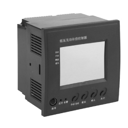
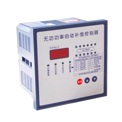
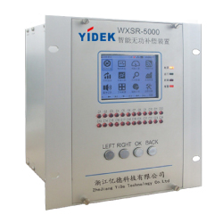
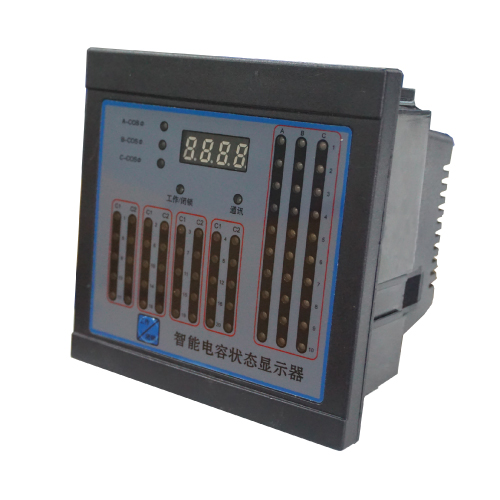
Smart Capacitor Status Indicator (hereafter referred to as the indicator). It is the latest development of the company, and is used in conjunction with the company's intelligent integrated power capacitors (hereinafter referred to as smart capacitors) to replace the traditional capacitor working status indicator and power factor meter. The product has high integration degree, beautiful appearance, universal instrument size, convenient installation and simple wiring, which can greatly improve the production efficiency of the whole cabinet and improve the overall product quality.

Second, the function description
1. 70 bright double-color LED indicators are integrated on the display panel. The three-phase total compensation system can display 30 sets of complementary smart capacitors. The hybrid compensation system can display 10 discrete intelligent capacitors and 20 shared smart capacitors. , dynamic display, low power consumption, high brightness.
2, the display uses two-color high-brightness LED lights, the green indicator light indicates the smart capacitor online status, the red indicator light indicates that the capacitor has been put, so that the smart capacitor working state is clear at a glance.
3. Adopt digital communication mode to exchange information with intelligent integrated power capacitors, automatically collect capacitance status signals and quickly refresh the display.
4. Self-contained communication fault detection, the communication lights are flashing interval during normal communication. When the communication bus is faulty or there is no communication, the communication light does not flash, prompting to check the communication line.
5. The communication interface adopts plug-in type, which is convenient to connect with smart capacitors. Users only need to connect 380V power cord.
6. It is convenient to control the automatic switching of the smart capacitor through the “Work/Latch” button; the “Work/Latch” indicator is green, indicating normal operation; the red indicates that the input is prohibited, and when the capacitor has been put in, it can be quickly removed.
7, can display real-time power factor, power factor indicator, red for capacitive, green for sensibility.
Third, the interface display instructions
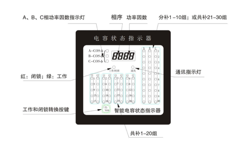
Fourth, the use of the environment
Altitude ≤ 3000m, humidity ≤ 90% (20 ° C), ambient humidity -20 ° C - 60 ° C,
The atmospheric pressure is 79.5-106 kPa, there is no flammable and explosive medium, and there is no conductive dust and corrosive gas.
Five, technical parameters
Rated voltage: 50HZ, 380V ± 20%;
Rated power consumption: no more than 3VA.
Sixth, mechanical installation and electrical wiring
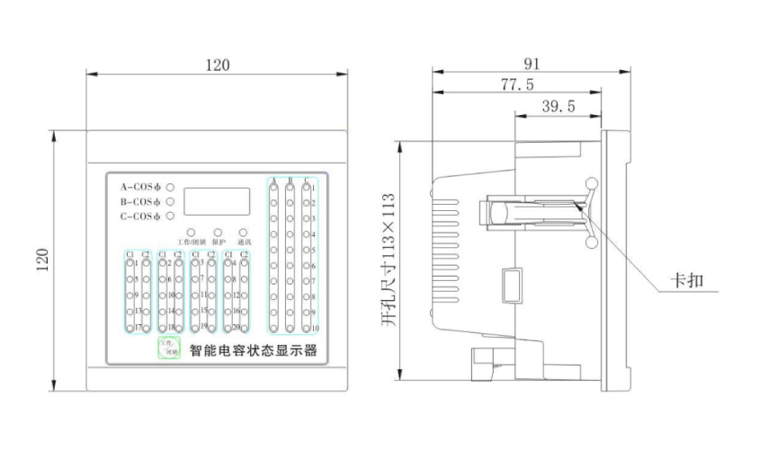
1. Mechanical installation: Open the square hole of 113X113mm on the cabinet door of the capacitor cabinet, push the product into the square hole from the front, insert the two buckles “see figure” into the left and right installation slots of the product, and push the product panel sideways. Just tight.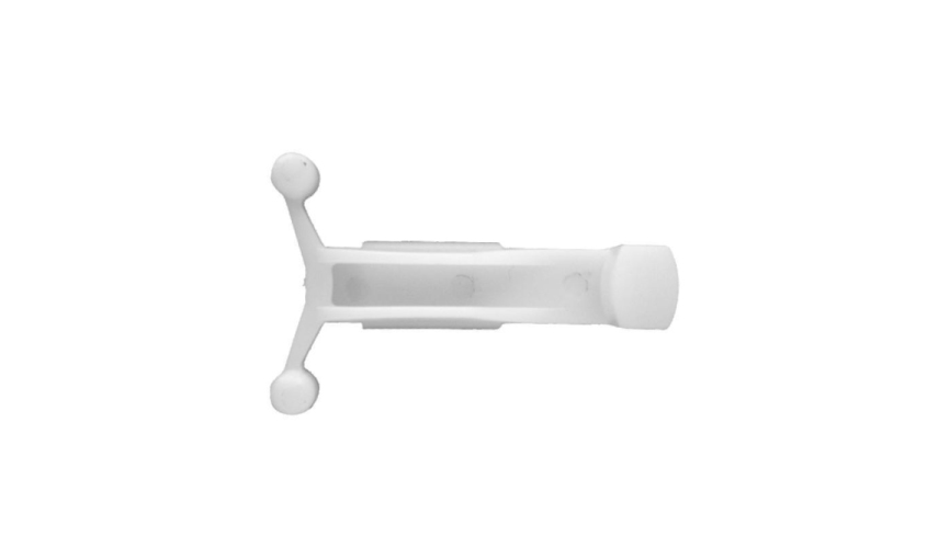
卡扣实物图
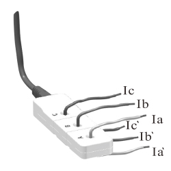
2, electrical wiring: electrical wiring as shown below the output terminal defines the exact wiring.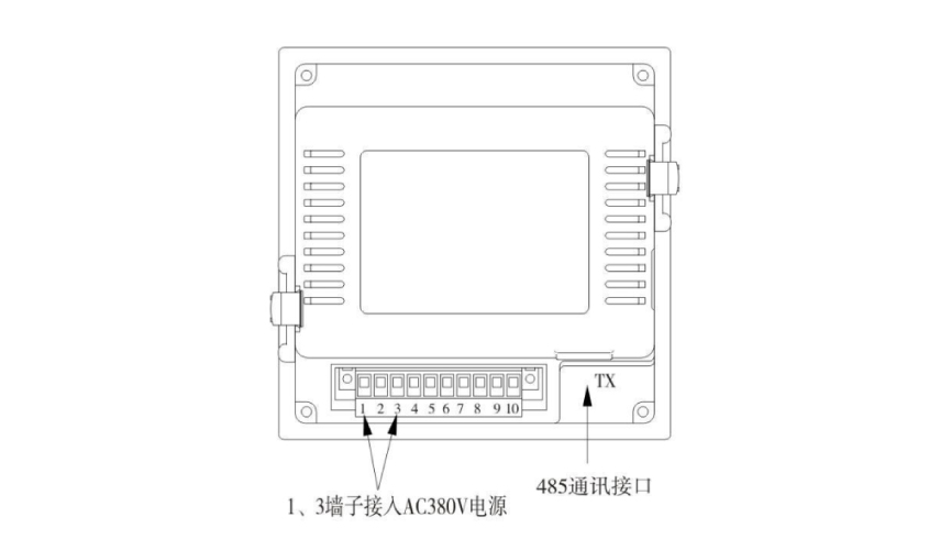
In the figure, the power supply is connected to 380V, and its fluctuation should be within the allowable range; the communication bus should be connected to the communication bus of the intelligent integrated power capacitor in the cabinet, that is, it can be connected with the communication port of the intelligent integrated power capacitor, as shown in the figure. :
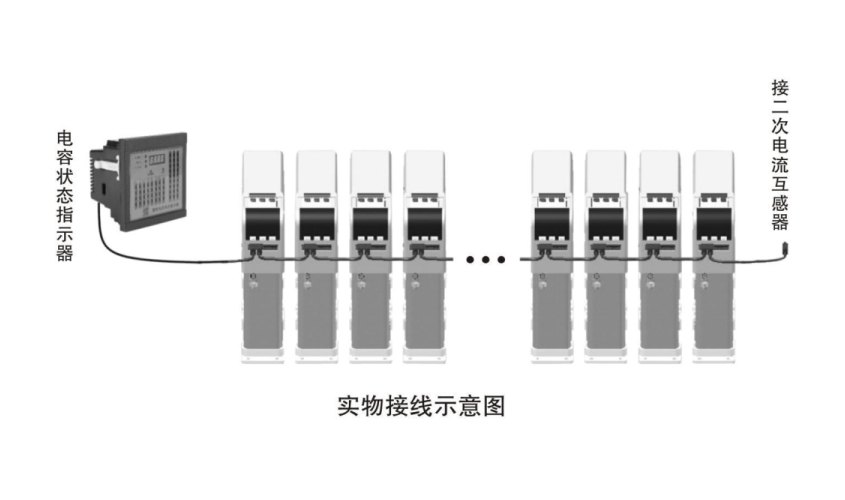
Seven, debugging and running
1. Check the wiring and confirm the error and turn on the power.
2, view the status indicator running process
The status indicator starts to display Y-ZT; after the smart capacitor is successfully networked (refer to the intelligent integrated power capacitor manual), the status indicator “Work/Latch” light is green; at the same time, the “Communication” light will flash once every 4S; after a while, the interface will display The current power factor value, the number of green lights in the status indicator is the same as the number of capacitors, and the surface change status indicator works normally.
3, "work / lock" state transition
The “Work/Block” indicator is green: the capacitor cabinet is in normal auto-compensation state.
That is, working status.
The “Work/Latch” indicator is red: the capacitor cabinet does not switch the smart capacitor according to the load change, ie it is in the locked state.
When the capacitor cabinet is overhauled or needs to cut off the capacitor that has been put into the cabinet, in the “working” state, press the “Work/Latch” button, the indicator will issue the blocking command, and the smart capacitors that have been put into the capacitor cabinet will be sequentially Cut off, and the “Work/Latch” indicator is red. In this state, the capacitor cabinet will not automatically input the smart capacitor. If you need to continue working, press the “Work/Lock” button again, the indicator will issue a command to release the lock status. The capacitor cabinet is in the automatic compensation state, and the “Work/Latch” indicator is green.
If you have any enquiry about quotation or cooperation,please feel free to email us at yidek@126.com or use the following enquiry form. Our sales representative will contact you within 24 hours. Thank you for your interest in our products.
- Subject:
- *Name:
- *Email:
- Company Name:
- Tel:
- Fax:
- Country:
- Message:


 E-mail:
  Tel: 400-8262-889
 Fax: 0577-85600699
 Contact: Mr. Ji
 Skype Online
 yidek@126.com
 Product Manual
 400-8262-889
 Problem
 Product Case
 Product Certificate
 Relevant information